
FRP Winding Process
Introduction
Fiber winding is one of the main manufacturing processes for resin-based composite materials. It is a method in which continuous fiber roving or cloth tape is impregnated with resin glue under controlled tension and predetermined linear shape, and then continuously wound on a core mold or lining corresponding to the inner cavity size of the product, and then cured at room temperature or heating conditions to form a product of a certain shape.
The development of fiber winding technology is closely related to the development of reinforcing materials, resin systems and process inventions. Although there was a process of adding longitudinal bamboo silk and circumferential silk to long wooden poles and then impregnating lacquer to make long weapon poles such as halberds and halberds in the Han Dynasty, it was not until the 1950s that fiber winding technology truly became a composite material manufacturing technology.
In 1945, the fiber winding technology was first used to successfully manufacture a springless wheel suspension device, and the first fiber winding machine was invented in 1947. With the development of high-performance fibers such as carbon fiber and aramid fiber and the emergence of microcomputer-controlled winding machines, fiber winding technology has developed rapidly as a composite material manufacturing technology with a high degree of mechanized production. It has been applied in almost all possible fields since the 1960s.
Section 1 Overview
Characteristics and Classification of Winding Molding Process
Characteristics of Winding Molding Process
As a commonly used composite material molding method, the characteristics of winding molding process include:
It is easy to realize the molding of high specific strength products. Compared with other molding process methods, the fibers in the composite material products molded by winding process are straightened and arranged in the specified direction with high neatness and precision. The products can give full play to the strength of the fibers, so the specific strength and specific stiffness are high. For example, the specific strength of ordinary glass fiber reinforced composite materials is three times that of steel and four times that of titanium.
It is easy to realize the equal strength design of products. Since the direction, layer and number of fiber arrangement can be determined according to the load-bearing requirements during winding, it is easy to realize equal strength design and the product structure is reasonable.
The manufacturing cost is low and the product quality is highly repeatable. The reinforcing materials used in winding products are mostly continuous fibers, untwisted rovings and weftless tapes, which do not need to be woven, thereby reducing the process and reducing the cost. At the same time, it also avoids the stress concentration at the interweaving points of the cloth pattern and the ends of the short fibers. The fiber winding process is easy to mechanize and automate, with high and stable product quality, high productivity, and convenient for mass production.
It is suitable for the manufacture of corrosion-resistant pipes, storage tanks, high-pressure pipes and containers, which is beyond the reach of other process methods.
Although the winding molding process is currently one of the most mechanized and automated processes among various composite molding processes, and can produce products with excellent performance, it also has the following limitations:
Bubbles are easily formed during the wet winding process, resulting in excessive pores in the product, thereby reducing the interlaminar shear strength, compression strength and anti-instability ability. Therefore, it is required to use more active diluents as much as possible during the production process, control the viscosity of the glue, improve the wettability of the fiber, and appropriately increase the fiber tension, so as to reduce bubbles and porosity.
The stress concentration around the opening of the wound composite product is high, and the interlaminar shear strength is low. Cutting, drilling or grooving for opening to connect accessories will reduce the strength of the winding structure. Therefore, it is required that the structure design is reasonable, and destructive processing such as cutting and drilling should be avoided as much as possible after the product is fully cured. For composite products that really need to be opened or grooved, local reinforcement measures need to be adopted.
(3) There are limitations on the shape of the molded product, and it is not suitable for the manufacture of parts with concave curved surfaces (double negative curvature curves). So far, most of the winding products are cylinders, spheres and certain positive curvature rotational bodies, such as tubes, tanks, elliptical transport tanks, etc. The winding rules and winding equipment for non-rotating bodies or negative curvature rotational products are relatively complex and are still in the research stage.
Classification of Winding Molding Process
Fiber winding molding process is usually divided into three types according to its process characteristics:
Dry winding molding process
After the continuous glass fiber roving is impregnated with resin, it is dried at a certain temperature for a certain period of time to remove the solvent and transfer the resin glue from stage A to stage B. Then the yarn is wound into a spindle. During winding, the pre-impregnated yarn tape is directly arranged on the core mold according to the given winding rule. This molding method is called dry winding molding process.
The quality of products made by this method is relatively stable, the winding speed can be increased (up to 100-200m/min), the process is easy to control, the equipment is relatively clean, and the labor hygiene conditions can be improved. This process method is easy to realize mechanization and automation. This process requires that the curing agent used should not sublimate or volatilize when the yarn is dried. In particular, the resin matrix system that uses high temperature curing such as anhydride and DDS often has a poor inner layer and rich outer layer of the product.
Some surfaces have many or even large bubbles and the surface is not smooth. In addition, since each fiber bundle impregnated with resin glue is stretched like a continuous and uniform thin sheet during yarn winding, it needs to be pre-impregnated, dried and wound. Therefore, the winding equipment is complex and the investment is large.
Wet winding molding process
The continuous glass fiber roving or glass cloth tape is impregnated with resin glue and then directly wound onto the core mold or lining to form a reinforced plastic product, and then cured. The molding method is called wet winding molding process.
The wet winding process equipment is relatively simple, and the requirements for raw materials are not strict, so different materials can be easily selected. Since the yarn is wound immediately after being dipped in glue, the quality of the yarn is not easy to control and inspect. At the same time, there is still a large amount of solvent in the glue solution, which is easy to produce bubbles during solidification, and the tension of the fiber during the winding process is also difficult to control.
Each link in the winding process, such as the dip roller, tension controller, and wire guide head, often requires maintenance and continuous cleaning to keep them in good working condition. If fiber entanglement occurs in a certain link, it will inevitably affect the entire winding process and product quality, and sometimes cause waste.
Semi-dry winding molding process Compared with the wet method, this process adds a drying process. Compared with the dry method, it shortens the drying time and reduces the drying degree of the rubber yarn. The winding can be carried out at room temperature. This molding process not only removes solvents and increases winding speed, but also reduces equipment and improves product quality.
Current Status and Development of Winding Molding Process
At present, winding products are used in both military and civilian fields. Military products are characterized by high performance and precise winding structure. The main civilian products include storage tanks, pipes and pressure vessels. In particular, the application of on-site winding technology has solved the problem of the size limitation of large fiber winding storage tanks in the past, greatly broadening the application scope of winding products. The commissioning of sand-filled fiber winding pipelines has opened up the application of FRP pipes in water supply systems.
Fiber winding can achieve the best product performance through the optimization of reinforcing materials, substrates and process structures. It is a relatively advanced FRP molding process, but there are still many problems that need to be further studied and solved:
In terms of structural design, the combination of winding process and structural design is still not close enough and should be further strengthened. The reasonable product structure form and design parameters determined by the structural design should be used to finally determine a reasonable process system to improve product quality, production efficiency and technical and economic indicators.
In terms of raw materials, the research on material properties still needs to be deepened, such as the strength of reinforcing materials, the elongation of resins, high temperature resistance, corrosion resistance and processability.
The development of automated winding equipment needs to be improved to ensure the maximum stability of the production process and the reliability and durability of the products, and to improve labor productivity.
Since the changes in raw materials and process have a great impact on product performance, it is also necessary to inspect and manage all links in the entire process from raw materials to products, and establish a sound and strict quality inspection and management system.
Section 2 Principle of Winding Molding Process
The analysis of the principle of winding molding process mainly studies the winding law, that is, the law of relative movement between the wire guide head and the core mold, so as to ensure that the fiber is wound around the core mold evenly, stably and regularly. Through the study of the winding law, the quantitative relationship between the structural size and line shape of the product and the relative movement between the wire guide head and the core mold can be found, so as to determine the optimal winding process system for the specific product.
Classification of Winding Laws
No matter what form of winding, it can be classified into three categories: circumferential winding, plane winding and spiral winding.
Circumferential Winding.
Circumferential winding is winding along the circumferential direction of the container. During winding, the core mold moves at a uniform speed around its own axis, and the wire guide head moves in the barrel section parallel to the axis of the core mold. For each rotation of the core mold, the wire guide head moves a yarn sheet width. This cycle continues until the yarn pieces are evenly distributed on the surface of the core mold cylinder section, as shown in the following figure:

The characteristic of circumferential winding is that the winding can only be carried out on the barrel section and cannot be wound on the end cap. Adjacent yarn sheets are connected but not overlapped, and the fiber winding angle is usually between 85° and 90°. In order to make the yarn sheets cover the surface of the core mold one by one, it is necessary to ensure the translation of the core mold and the wire guide head and ensure the coordination of the two movements.
Plane Winding.
During plane winding, the wire guide head performs uniform circular motion in a fixed plane, and the core mold rotates slowly around its own axis. For each rotation of the wire guide head, the core mold rotates a small angle, which is reflected on the surface of the core mold as a yarn sheet width. The yarn sheet forms an angle of 0° to 25° with the longitudinal axis of the core mold, and is tangent to the two end holes, and is continuously wound onto the core mold in sequence. The yarn sheets are arranged without fiber crossing, and the fiber winding trajectory is a single circular plane closed curve.
The speed ratio of plane winding refers to the ratio of the number of core mold rotations to the number of wire guide head rotations per unit time. The angle between the yarn sheet and the longitudinal axis is called the winding angle (α), as shown in the following figure:


(Annular winding) In the formula, r1, r2 are the radii of the two end holes; L is the length of the barrel; Le1, Le2 are the heights of the two ends.
If the two end holes are the same and the end heights are the same, then:

Plane Winding
The arc length of a yarn sheet with a width of b and a winding angle of α on the parallel circle of the core mold is , and the core mold rotation angle corresponding to this arc length is . If the time for the guide wire head to rotate one circle is t, then the speed ratio of the plane winding is:

Spiral Winding.
Spiral winding is also called geodesic winding. During winding, the mandrel rotates at a constant speed around its own axis, and the wire guide moves back and forth along the axis of the mandrel at a specific speed. In this way, spiral winding is achieved on the barrel and head of the mandrel, and the winding angle is about 12° to 70°, as shown in Figure 7-3.

Spiral Winding
In spiral winding, the fiber winding is not only carried out on the barrel section, but also on the head. The winding process is as follows: the fiber starts from a certain point on the circumference of the pole hole at one end of the container, goes around the head along the curve tangent to the pole hole circle on the head surface, and goes around the cylindrical section along the spiral trajectory, enters the head at the other end, and then returns to the cylindrical section, and finally goes back to the head where the winding starts, and so on, until the surface of the core mold is evenly covered with fibers.
It can be seen that the trajectory of spiral winding is composed of the spiral line of the cylindrical section and the spatial curve tangent to the pole hole on the head, that is, during the winding process, if the yarn sheet is wound on the core mold with a right-handed thread, it will be wound on the core mold with a left-handed thread when returning.
The characteristic of spiral winding is that each bundle of fibers corresponds to a tangent point on the circumference of the pole hole; adjacent yarn sheets in the same direction are connected but not intersected, and fibers in different directions intersect. In this way, when the fibers are evenly wrapped around the surface of the core mold, a double-layer fiber layer is formed.
Analysis of sSpiral Winding Law
At present, two main analysis methods are used to study the winding law: standard line method and tangent point method. The basic point of the standard line method is to study the structural dimensions of the product and the relative motion law of the wire guide head and the core mold through a certain characteristic line on the surface of the container – the “standard line”. This method is intuitive and easy to learn, but the analysis and calculation process is relatively complicated and the accuracy is not very high.
The tangent point method is to study the distribution law of the corresponding tangent points of the winding line type on the pole hole and the relationship between the fiber winding core mold rotation angle and the line type and speed ratio. This method is highly theoretical and the mathematical derivation is relatively rigorous. Although the starting points of these two analysis methods are different, there is no essential difference. The following will use these two methods to analyze the spiral winding law.
Explanation of Terms
Standard Line.
During spiral winding, the core mold rotates around its axis, and the wire guide head reciprocates parallel to the axis of the core mold. The fiber led by the wire guide head starts from a certain point on the core mold. After several reciprocating motions, the fiber winds back to the original point. In this way, the first yarn laying is completed on the core mold, which is called the standard line.
The arrangement of standard wires is different, and the line type and winding law are different. Therefore, the standard wire is the basic line type that reflects the winding law. The figure below is the expansion diagram of the spiral winding standard wire when n=4 and k=1.

The expansion diagram of the standard line of spiral winding when n=4 and k=1
As can be seen from the figure, the fiber starts to be wound from point A, and its direction is A→B→polar hole II→C→D (coincides with A)→polar hole I→E→C→polar hole II→B→E→polar hole II→back to the starting point A. We call this wiring the standard line. Spiral winding is always carried out along a certain standard line. The only difference is that after each standard line is wound, the fiber should miss a yarn sheet width. This process continues until the surface of the core mold is covered with fibers. At this time, it is called a cross-winding cycle, and the display on the core mold is two layers of cross-fibers.
Crossover.
The intersection of the wound fibers that are not parallel to each other on the standard line is called a crossover. When the same structural size of the container adopts different winding rules, the number and position of the crossover points are also different. Points A, B, C, D, (A), and E in the figure are crossovers.
Crossover.
After the spiral winding goes through a cycle, the trace formed by the crossover points is called a crossover. The line connecting A, E, D and B, C in the figure is the intersection zone. It is a section line perpendicular to the axis. At both ends of the barrel, at a certain distance from the intersection line of the barrel and the head, there is a cross-sectional circular line that coincides with the intersection zone. We call this cross-sectional circular line the reference line.
Common Symbols
Lc——The length of the barrel lining of the container;
D——The diameter of the lining;
Rx——The radius of the polar hole at the head (the coordinate value of the head curve on the x-axis);
Ry——The y-axis coordinate value corresponding to the value of Rx;
α——The winding angle, which indicates the angle between the direction of the fiber on the mandrel and the axis of the mandrel;
β——The wrap angle of the standard line at the head. It indicates the angle that the mandrel rotates from the fiber entering the head to winding out of the head;
γ——The entry angle of the standard line in the barrel section. The angle that the core mold rotates when the fiber is wound from one end of the cylinder to the other end;
n——The number of equal divisions of the circumference of the cylinder;
Li——The distance between the reference lines at both ends of the cylinder;
di——The distance from the reference line to the boundary line between the cylinder and the head;
J——Number of plane winding cycles;
K——Longitudinal fiber utilization coefficient (K=0.7~0.8);
f——Average strength of each bundle of fiber, 79.8N/bundle;
Nθ, Nf——Number of fiber bundles of circumferential and planar winding yarn sheets (bundles/strips);
m, M——Density of yarn sheets during circumferential winding, strips/cm;
P——Internal pressure of the container, 710-1MPa;
R——Radius of the container.
Calculation Formula:
①Calculation of the number of plane winding cycles J:

(When n=4 and k=1, the spiral winding standard line expansion diagram)
② Calculation of the number of circumferential winding layers n:

(When spirally winding standard wire)
Analyze the Spiral Winding Law Using the Standard Wire Method
Any type of winding process requires the core mold and the wire guide to move relative to each other in different rules. Therefore, the analysis of the winding law is to find the functional relationship between the product structure size and the winding parameters, such as winding angle, speed ratio, etc. The following analysis takes the cylindrical container under internal pressure as an example.


When studying the relationship between the fiber advance angle γ and the winding angle α in the barrel section, for the convenience of analyzing the problem, the spiral winding standard line expansion diagram is simplified to the following Figure 7-5, from which it can be seen that

Figure 7-5 Spirally Wound Standard Wire


The winding angle of the head portion during spiral winding.
There are two cases for the winding angle of the head portion, which are described as follows:
The head portion is plane winding.
The fibers wound on the head portion are in the same plane. In this case, the head winding angle αD at the connection between the head portion and the barrel (see the spiral winding standard line expansion diagram) is:


② For the case where the head is wrapped with geodesic wire, the following can be obtained from equations (7-9) and (7-11):


The wrap angle β of the standard line at the top of the head Assume that the angle γ1 is on the standard line. When the fiber is wound from the reference line A to the boundary line β between the cylinder and the head, the angle that the core mold rotates.
So
Figure 7-6 shows the diagram of the spirally wound standard line at the end of the container


Speed ratio definition The speed ratio is the ratio of the number of revolutions N of the core mold to the number of times the guide wire head goes back and forth around the core shaft j per unit time. In any mechanical winding, to achieve a certain winding law, it is mainly achieved by determining the speed ratio.
That is


It can be seen that the speed ratio i, for spiral winding, is the ratio of the original core mold rotation number N and the number of round trips of the guide wire head j, which becomes the relationship between n and K in this specific winding law. And it is independent of other parameters.
(ⅶ) Determination of n and K When selecting the winding law, n and K cannot be determined arbitrarily. Practice has shown that factors such as the head wrap angle β and the barrel advance angle γ should be taken into account, and the relationship must be satisfied

These parameters are also directly related to the container size, winding angle α and the distance di between the reference line and the boundary line between the barrel and the head. Only by comprehensive consideration and research can we select the appropriate n and K values, make the selected winding law adapt to the container, and avoid abnormal situations such as fiber slippage and deflection during winding.
Analyze the Spiral Winding Law by the Tangent Point Method
As we have introduced before, spiral winding is a continuous fiber winding process. The trajectory of the wound fiber is composed of the spiral line of the barrel part and the space curve tangent to the head part and the pole hole.
The line type of spiral winding is related to the position and number of the tangent points, that is, it is related to the position of the fiber tangent point on the circumference of the pole hole of the head. Therefore, the study of the law of fiber distribution on the surface of the core mold can be solved by studying the distribution and distribution law of the tangent points on the circumference of the pole hole. This is the basic idea of using the tangent point method to describe the spiral winding law.
Line Type
The so-called line type is the arrangement pattern of continuous fiber winding on the surface of the core mold. When describing the line type of spiral winding by the tangent point method, the main purpose is to link the line type with the number of tangent points and the distribution law for research.
Conditions for the Fiber to be Evenly Distributed on The Mandrel Surface
The concept of a complete cycle. The fiber wound on the mandrel is introduced by the wire guide from a certain point on the mandrel. After several round trips, the wire guide returns to the original starting point. Such a wiring is called a standard line. Completing a standard line winding or completing a winding that coincides with the initial tangent point is called a complete cycle.
It can be seen from this that in order to make the fiber evenly wrapped around the mandrel surface, several standard lines formed by continuously wound fibers are required. In other words, several complete cycles of winding are required to achieve this. The arrangement type of the standard line, that is, the winding pattern characteristics include tangent points, intersection points, cross bands and their distribution laws. It reflects the pattern characteristics of the entire winding. Therefore, the standard line is the basic line type that reflects the winding law.
The Number and Distribution of Tangent Points in a Complete Cycle Winding
The concepts of temporal adjacency and positional adjacency of tangent points.
Temporal adjacency: two tangent points that appear successively in time order on the circumference of the polar hole. There are only two cases of their relative positions. One is that the two tangent points are closely spaced and no other tangent points are added, and the two tangent points are called positional adjacency; the other is that other tangent points are added between the two tangent points, and the two tangent points are called positional non-adjacent. But they both indicate the position of the tangent points and the order of their appearance.
Single tangent point and multiple tangent points.
There are two cases to complete a complete cycle winding: the first case is that the tangent points adjacent to the starting tangent point are also adjacent in time order. Therefore, before the tangent point adjacent to the starting tangent point appears, there is only one tangent point on the circumference of the polar hole, so it is called a single tangent point. The second case is that the points adjacent to the starting tangent point are not adjacent in time order.
That is to say, before the tangent point adjacent to the starting point appears, there are more than two tangent points on the circumference of the pole hole. This situation is called multiple tangent points (the number of tangent points n = 2, 3, 4…).
Since the core mold rotates at a uniform speed and the wire guide head has the same round trip time each time, the circumference is divided equally by several tangent points on the circumference of the pole hole. The arrangement order of single tangent points and two tangent points is shown in Figure 7-7.

Figure 7-7 Tangent point line type on the head polar hole circle
The following is a study of the arrangement order of the tangent points that divide the circumference equally within a complete cycle. Obviously, when n=1 and n=2, the arrangement order of the tangent points on the polar hole circumference is fixed. When n=3, before the tangent point adjacent to the starting tangent point position appears, n≥3 tangent points have appeared on the polar hole circumference, so they have different arrangement orders. Taking n=3, 4, and 5 as examples, their arrangement order is shown in Figure 7-8.

It can be seen that different line types have different numbers of tangent points and different order of arrangement of tangent points.
The condition for the fiber to be evenly distributed on the surface of the core mold. Since each bundle of yarn on the core mold corresponds to a tangent point on the circumference of the pole hole. Therefore, as long as the following conditions are met, it can be achieved that after several complete cycles of winding, the yarn can be evenly distributed on the entire surface of the core mold one by one.
The tangent points that complete a complete cycle divide the angle of the core mold rotation equally, that is, the tangent points are evenly distributed on the circumference of the pole hole.
The distance between the yarns corresponding to the two adjacent tangent points on the barrel section is equal to the width of a yarn. Obviously, due to condition ①, the distance between the yarns that are successively wound through the corresponding tangent points on the barrel is also equal to the width of a yarn.
Therefore, the arrangement law of the fiber winding evenly covering the surface of the core mold can be solved by studying the arrangement law of the fiber winding in a complete cycle. And the line type that completes a complete cycle of winding law can be analyzed by the distribution law of the tangent points on the circumference of the pole hole.
Next, we will find out the motion relationship between the core mold and the guide wire head that can meet the above two conditions.
The relationship between the core mold rotation angle of fiber winding, that is, the winding center angle and the line shape. When a complete cycle of winding occurs, that is, when a tangent point adjacent to the starting tangent point appears, the core mold rotation angle is represented by θ.
When the guide wire head goes back and forth once, that is, when a tangent point adjacent to the starting tangent point appears, the core mold rotation angle is represented by θn.
When the guide wire head travels a single thread, that is, one-way line winding, the core mold rotation angle is represented by θt. Then

Next, we derive θn:
Single tangent point line type.
When the single tangent point line type is wound again, the tangent points adjacent to the starting tangent point position are also adjacent in time sequence, thus forming the winding law of the single tangent point line type.


Two-tangent point line type.
The two-tangent point line type also belongs to the multi-tangent point line type. The so-called multi-tangent point line type means that the tangent points adjacent to the starting tangent point are not adjacent in time sequence, that is, when the first tangent point adjacent to the starting tangent point appears, there are already several tangent points on the end cap pole hole – the initial tangent point. This winding law is collectively called the multi-tangent point line type.
According to different initial conditions, the multi-tangent point line type is divided into two-tangent point, three-tangent point…n-tangent point line type. For the two-tangent point line type, it means that the tangent point adjacent to the starting tangent point position in time sequence is separated from the starting tangent point by one tangent point in time sequence, that is, it constitutes a two-tangent point line type. The two-tangent point line type diagram is shown in Figure 7-10.

As can be seen from the figure, the tangent point 3 adjacent to the starting tangent point 1 is separated by a tangent point 2 in time sequence; and the tangent point 4 adjacent to the tangent point 2 is separated by a tangent point 3 in time sequence. Since the tangent point 3 adjacent to the starting tangent point 1 is separated by a tangent point 2 in time sequence, the fiber starts to wind from the tangent point 1.
When it is wound to the tangent point 2 adjacent to the time sequence, the central angle of the core mode is 360°/2, that is, the polar hole circumference is equally divided by two tangent points; when the fiber is wound to the tangent point 3 adjacent to the tangent point 1, the core mode rotates by 360°/2 again and misses a tiny amount Δθ.
Therefore, in the two-tangent point line type, the tangent point adjacent to the initial tangent point position on the polar hole circumference appears, and the core mode must rotate by at least 360°/2±Δθ/2; or add an integer multiple N of 360°, so the winding law of the two-tangent point line type should be:

Because in the two-tangent point line type, the fiber is wound from the starting tangent point 1, and when the core mold rotates 360°/2, the fiber is wound to the position of tangent point 2. When the core mold rotates 360°/2 again, the fiber is wound to the tangent point 3 adjacent to the position of tangent point 1, and misses a tiny amount of Δθ. Therefore, Δθ is missed after rotating two 360°/2, so Δθ/2 is missed every time it rotates 360°/2.
Three-Tangent Point Line Type.
The so-called three-tangent point line type refers to the tangent points adjacent to the starting tangent point position, which are separated from the starting tangent point by two tangent points in time sequence, forming a three-tangent point line type. The three-tangent point line type is shown in Figure 7-11.

As can be seen from the figure, the tangent point 4 adjacent to the starting tangent point 1 is separated from the tangent point 1 by two tangent points in time sequence, namely, tangent point 2 and tangent point 3; similarly, the tangent point 5 adjacent to the tangent point 2 is separated from the tangent point 2 by two tangent points in time sequence, namely, tangent point 3 and tangent point 4; the tangent point 6 adjacent to the tangent point 3 is separated from the tangent point 3 by two tangent points in time sequence, namely, tangent point 4 and tangent point 5.
Therefore, the line type of the three tangent points is equally divided by the three initial tangent points on the circumference of the polar hole. Therefore, when the fiber is wound from the starting tangent point to the tangent point 2 adjacent in time sequence, the core mold must rotate at least 360°/3, or add an integer multiple N of 360°. Considering the misalignment of the fiber, a trace Δθ1 should also be introduced, so the winding law of the three tangent point line type is:

Linear rules of arbitrary tangent points.
Above we have analyzed the winding rules of single-tangent point line types, two-tangent point line types, and three-tangent point line types. Now let us expand it to the line types of arbitrary tangent points, that is, how about the line types of n-tangent points? For the line type of n-tangent points, the tangent points adjacent to the starting tangent point are separated by (n-1) tangent points in time sequence, thus obtaining the line type of n-tangent points. Based on the above, we can infer that the winding rule of the line type of n-tangent points is:

In the formula, θn represents the central angle of the core mold when winding from the tangent point n on the circumference of the pole hole to the tangent point (n+1) adjacent in time sequence.
Every time the winding wire head passes through the pole hole, the fiber has a tangent point on the pole hole, and the θn used also represents the central angle of the core mold when the wire head goes back and forth once. Therefore, the above formula is the basic mathematical expression for analyzing the winding law using the “tangent point method”.
However, this method is also inappropriate. In the previous discussion, we actually assumed that the order in which the initial tangent points appear is sequential, and their arrangement order is not analyzed. In the actual winding process, in addition to the single-tangent point line type and the double-tangent point line type that do not have the initial tangent point arrangement, the line type with more than three tangent points also has an initial tangent point arrangement order problem.
In the formula, n represents the number of tangent points of the line type, that is, the number of all tangent points adjacent in time sequence before the first tangent point adjacent to the starting position appears on the circumference of the pole hole. (n is 1, 2, 3…). N represents the integer multiple of 360° that the core mold rotates from the initial tangent point n to the tangent point (n+1), which is a positive integer including zero, i.e. 0, 1, 2, etc.
When n≥3, that is, the line type with more than three tangent points, before the tangent point adjacent to the initial tangent point appears, there are more than 3 initial tangent points on the circumference of the pole hole, which leads to a problem of the order of arrangement of the initial tangent points.
As mentioned above, there are two arrangement orders for three tangent points, two arrangement orders for four tangent points, and four arrangement orders for five tangent points. Therefore, the three tangent point line type has:

The order of the circular arrangement is different, or in other words, the central angle that the core mold must rotate through when the wire guide moves back and forth once is different. The K value is a positive integer, K = 1, 2, 3…n-1. The K value requirement should make K/n the simplest proper fraction.
In summary, in a complete cycle, if the number of tangent points is different, the fiber arrangement order and pattern characteristics (number of intersections, cross bands, number of nodes, etc.) are different, that is, the line type is different, and the core mold rotation angle is different when the wire guide moves back and forth once; if in a complete cycle, the number of tangent points is the same but the order of tangent point arrangement is different, the fiber arrangement characteristics (line type) are also different, and the core mold rotation angle of the wire guide head is also different. That is to say, the core mold rotation angle of the wire guide head for one round trip has a strict corresponding relationship with the winding line type. Therefore, our core mold rotation angle of the wire guide head for one round trip is


The relationship between the speed ratio and the line type.
The line type and speed ratio are both related to the winding law. The line type refers to the arrangement law of the fibers on the surface of the mandrel, while the speed ratio refers to the law of relative movement between the mandrel and the guide wire head. They are two completely different concepts. However, as mentioned earlier, different line types strictly correspond to different speed ratios. Therefore, we define the line type to be numerically equal to the speed ratio, that is, the speed ratio value is used as the “code” of the line type, namely:


In order to avoid fiber slipping, negative values are usually taken. In actual calculation, i is taken to 4~6 decimal places.
- Linear Design
Calculation of Stable Winding Core Mold Angle.
For a specific part, how to achieve product molding based on the winding process under the given conditions of original geometric dimensions, container working pressure and pole hole? This requires how to select the core mold angle θn during the winding process, because it corresponds to a fixed linear shape and speed ratio.
We already know that different n, N, and K correspond to different θn, that is, there are several core mold angles θn that meet the two conditions of fiber regular and uniform distribution on the core mold surface. However, for a certain product, not all θn are suitable.
If any θn is selected according to Table 7-1 and the speed ratio is fine-tuned ±Δθn for winding, although the two conditions of uniform distribution are met, the purpose of uniform distribution may not be achieved. Because the position of the fiber on the container surface and the head surface is not necessarily stable, fiber slipping may occur.
Theoretically, the necessary condition for the head to not slip is to make the fiber located on the geodesic on the head surface. Therefore, the third condition for the fiber winding to be regularly and evenly distributed on the mandrel surface is generated – the condition of stable fiber position, which requires that each bundle of fibers wound on the mandrel surface is the geodesic of its corresponding surface. Next, the problem of determining the geodesic of a cylindrical container with a head is discussed.
The helical line of any winding angle in the barrel section is a geodesic; winding at the head requires


Where L is the length of the cylinder;
D is the diameter of the cylinder;
α is the winding angle;
W is the pitch.
(ii) Solving β. The calculation of the core mold rotation angle corresponding to the geodesic winding of the head surface is relatively complicated. And the winding trajectory is currently a plane curve that approximates the geodesic. Therefore, we usually use the plane assumption method to calculate the core mold rotation angle of the head part.

As shown in Figure 7-15, a plane is made through the two intersection points (A and D) of the fiber on the equatorial circle, which is tangent to the polar hole circle (the tangent point is β). The intersection line (plane curve ABC) that intersects the head surface is the fiber winding trajectory. This plane is called the cutting plane, and the angle between it and the cylinder axis is α0. The rotation angle of the head winding mandrel is

Draw plane II through point D parallel to plane BHC, and its intersection with the section plane is DF. Draw plane I through point D, which is the tangent plane of the cylinder, and its intersection with the section plane is DE. DG is the intersection of planes I and II. Draw a plane through point G perpendicular to DG, and its intersections with planes I and II are EG and FG respectively, and its intersection with the section plane is EF.


It can be seen from this that for a single tangent point, when the line type is 1/1, the wire guide head goes back and forth once, the core mold rotates one circle, and the standard line has no intersection, as shown in Figure 7-16 (a). When the line type is 2/1, the wire guide head goes back and forth once, the core mold rotates two circles, and the standard line has only one intersection, as shown in Figure 7-16 (b), and the same applies to the others.

It can be seen that after winding the standard line, the number of intersections is related to the number of core mold rotations M. For a single-tangent line type, the number of intersections is equal to the number of core mold rotations minus 1, that is, xn-1=M-1. For a multi-tangent line type, after winding the standard line, the wire guide head must go back and forth many times, so the number of intersections is related to the number of times the wire guide head goes back and forth (the number of tangent points). For example, when the line type is 3/2, after winding the standard line, the core mold rotates 3 times, the wire guide head goes back and forth 2 times, and there are 4 intersections in total, that is, the number of intersections is equal to 2 times the number of core mold rotations minus 1, that is, xn-2=2(M-1), as shown in Figure 7-17.
When the line type is 4/3, after winding the standard line, the core mold rotates 4 times, the wire guide head goes back and forth 3 times, and there are 9 intersections in total, that is, the number of intersections is equal to 3 times the number of core mold rotations minus 1, that is, xn-3=3(M-1), as shown in Figure 7-18. The rest are similarly analogous. For a line type with n tangent points, the number of intersection points is equal to the number of core mode rotations minus 1 multiplied by the number of tangent points, xn=n(M-1).

Since each fiber corresponds to a tangent point on the circumference of the polar hole, the number of intersection points on the intersection circle is equal to the number of tangent points, so the number of intersections is yn = M-1.
It can be concluded that no matter what kind of line type, the number of intersections is the number of molecules in the line type (that is, the number of core mold turns after winding a complete cycle) minus 1. The number of intersections is the product of the number of intersections and the number of tangent points.
Distribution law of intersections and intersections From the continuity of the fiber, it can be seen that each fiber corresponds to a tangent point on the circumference of the polar hole. At the same time, the tangent points of the standard line wound at the same time divide the circumference of the polar hole equally. Therefore, the intersection points on the intersection circle divide the section equally, that is, the core mold rotation angle between two adjacent intersection points on the intersection circle is 360°/n.

Design of Winding Rules
Previously, the winding rules have been analyzed one by one using the standard line method and the tangent point method. The following is a discussion on how to select and design in actual production.
Requirements for Selecting Winding Rules
The winding angle α is required to be close to the geodesic winding angle. In order to better exert the strength of the glass fiber, the winding angle α should be close to 55°.
In order to avoid the fiber being suspended near the pole hole and affecting the head strength, the selected winding rule should not have too many intersections at the end of the pole hole.
The head wrap angle β should be close to 180°. Generally, β=160°~180° is selected, otherwise the fiber will slip on the head.
Steps to Select Winding Rules
(1) In general, the circumference of the barrel is divided into 4 equal parts, that is, n=4. If K=1, 2, 3, 4, 5 are taken respectively, there are 5 types of winding rules:
n=4, K=1;
n=4, K=2;
n=4, K=3;
n=4, K=4;
n=5, K=1;

Determine the Winding Law and Others
After the above calculations, list the corresponding winding parameters calculated for the above five types of lines. Then, according to the three selection principles of the winding law, combined with actual work experience, analyze and compare, after screening, a more reasonable winding law can be obtained, which is the true winding line type of this product.
According to the obtained speed ratio i value, consider the necessary yarn staggering during the winding process to provide a basis for the design of the winding machine.
Example
To wind an internal pressure vessel with a diameter of D=770mm, a barrel length of L=2930mm, a head hole diameter of d=385mm, and a head height of h=285mm, try to select the winding line type and speed ratio, and draw a standard line expansion diagram. Set the yarn sheet width b=5mm.
The Design Ideas are as Follows:
First, calculate the core mold rotation angle θn when the fiber is wound according to the geodesic trajectory and the wire guide head goes back and forth once (that is, a tangent point appears in the timing sequence adjacent to the starting tangent point). When winding at this speed ratio, it can ensure that the fiber wound on the surface of the core mold does not slip (stable). However, it does not meet the condition of being regularly and evenly distributed on the surface of the core mold. The line shape that meets this condition should be

The core mold rotation angles in the linear table calculated by this formula can meet the requirements of uniform distribution. However, for a specific product, not all core mold rotation angle values in the linear table can meet the fiber position stability conditions. How to resolve this contradiction? First, calculate the core mold rotation angle of the geodesic trajectory, and then find a value close to this value in the linear table 7-1 as the calculation data. Then adjust the size of the container. Winding with this speed ratio can meet both the uniform distribution conditions and the fiber position stability conditions.
So how to calculate the geodesic winding angle? We know that for the barrel section, any angle of the spiral is a geodesic, that is, it is stable (in fact, there is no need to consider the stability of the fiber winding on the barrel). The contradiction is concentrated on the head surface, and the geodesic equation on the head surface is
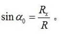
Where α0 is the winding angle outside the equatorial circle of the head. Obviously, the position of the fiber on the head or the shell is stable when the winding angle calculated by this formula is used. So there is


IF COMPOSITE MATERIAL IS NEEDED, PLEASE GET A HOLD OF US IN WHICHEVER WAY IS MOST CONVENIENT. WE WILL REPLY YOU WITHIN 24 HOURS.